| | A lifeboat build blog...........How a kit is made! |  |
|
+10tattooed Tug--Kenny scalloway41 phil winks pugwash AlanP HS93 intrepid75 Windy Footski 14 posters |
|
| Author | Message |
|---|
phil winks
Master


Posts : 583
Join date : 2011-06-12
Age : 68
Location : Taunton
 |  Subject: Re: A lifeboat build blog...........How a kit is made! Subject: Re: A lifeboat build blog...........How a kit is made!  Thu Jan 12, 2012 5:52 pm Thu Jan 12, 2012 5:52 pm | |
| Those vibratory multi tools are some thing else Neil, I've not used the "Worx" one but the German made "Fein" tool really is the mutts whatsits however not cheap about £300  | |
|
  | |
Guest
Guest
 |  Subject: Re: A lifeboat build blog...........How a kit is made! Subject: Re: A lifeboat build blog...........How a kit is made!  Thu Jan 12, 2012 7:24 pm Thu Jan 12, 2012 7:24 pm | |
| yeh.....I'm looking forward to using mine Phil....was going to use it today but the decals came from Becc and so I put them on, but not before getting an email from a tosser of a new manager at the charity I have just built the model boat Flying Christine for. we had an agreement 2 years ago that I'd build them the model absolutely free of charge and take it to Weymouth where they would book us on a ferry and we'd spend 7 nights in a self catering let and deliver it to them in guernsey.
got an email from this tosser today saying I could transport the model I had paid for at my expense to the ferry, pay my own ferry over and they would pay for me and my wife ONLY for two nights in guernsey....the round trip to weymouth is 600 miles from my home, and WTF do I do with my two young daughters whilst we make the trip.......I went ballistic, and told the eejit thet the could now sing for the model.........I am so absolutely incensed by this "manager's " jobsworth attitude....just cant believe it. |
|
  | |
phil winks
Master


Posts : 583
Join date : 2011-06-12
Age : 68
Location : Taunton
 |  Subject: Re: A lifeboat build blog...........How a kit is made! Subject: Re: A lifeboat build blog...........How a kit is made!  Thu Jan 12, 2012 8:42 pm Thu Jan 12, 2012 8:42 pm | |
| its sad when idiots get in the way of a good deed mate. we recently had a similar issue where the "overtones" performed free of charge at a benifit gig for the victims and families of the horendous crash on the M5 last nov the 4th and when the organisers tried to release a DVD of the gig Warner (who the own the label the overtones are signed to) decided they could not appear as they weren't getting the royalties sad or what??? any way back to your efforts on the life boats eh mate | |
|
  | |
Guest
Guest
 |  Subject: Re: A lifeboat build blog...........How a kit is made! Subject: Re: A lifeboat build blog...........How a kit is made!  Thu Jan 12, 2012 9:24 pm Thu Jan 12, 2012 9:24 pm | |
| yes matey..will be back on to it tomorrow.let me loose with my sonic sander.....sound like Dr Who, lol |
|
  | |
phil winks
Master


Posts : 583
Join date : 2011-06-12
Age : 68
Location : Taunton
 |  Subject: Re: A lifeboat build blog...........How a kit is made! Subject: Re: A lifeboat build blog...........How a kit is made!  Fri Jan 13, 2012 8:19 pm Fri Jan 13, 2012 8:19 pm | |
| | |
|
  | |
Guest
Guest
 |  Subject: Re: A lifeboat build blog...........How a kit is made! Subject: Re: A lifeboat build blog...........How a kit is made!  Fri Jan 13, 2012 8:37 pm Fri Jan 13, 2012 8:37 pm | |
| well, tomorrow is here and that sonic sander ripped through the filler in less time than it would have taken me to count to ten the number of cliche's on a Batman episode, lol ( for those who don't watch it, it's the finest of american cheese that you could ever wish to see, lol.channel 24 daytime) It would have taken me about an hour and many sanding pads if I'd have used a palm sander, but each boat took around 10 minutes....... I sanded the filler that had been used to fill the hollow left by the moulding of the protective belting so that I could glue a strip of 6 x 6 mm sprue to the edge of the bulwark, to eventually glue the deck edges to. Using2 part epoxy I glued pieces between the cross beams that had been pre sawn half way through to allow bending the timber to the contour and shape of the bulwarks. I held the strips whilst glueing with spring clamps. 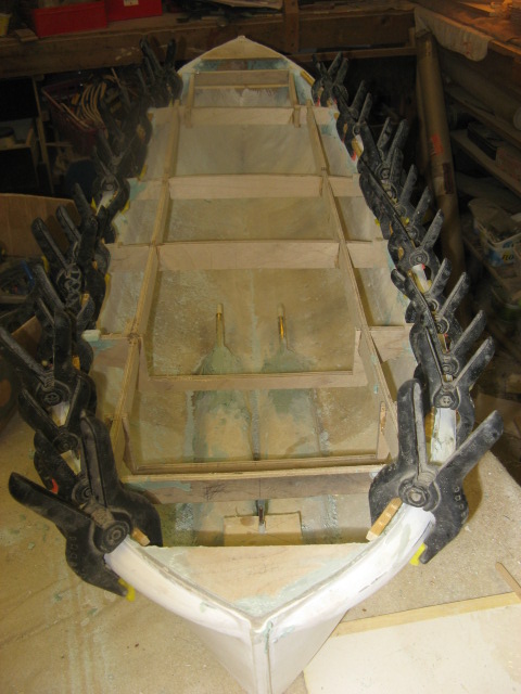    . |
|
  | |
phil winks
Master


Posts : 583
Join date : 2011-06-12
Age : 68
Location : Taunton
 |  Subject: Re: A lifeboat build blog...........How a kit is made! Subject: Re: A lifeboat build blog...........How a kit is made!  Sat Jan 14, 2012 8:42 pm Sat Jan 14, 2012 8:42 pm | |
| not suprised that your pleased with the sander Neil! Apparently the flush cutting saw won't cut fingers due to the short stroke it uses however when you see it charging through 2 inches of pine the desire to put that fact to the test tends to depart rapidly  | |
|
  | |
Guest
Guest
 |  Subject: Re: A lifeboat build blog...........How a kit is made! Subject: Re: A lifeboat build blog...........How a kit is made!  Sat Jan 14, 2012 8:52 pm Sat Jan 14, 2012 8:52 pm | |
| yes indeed phil...they look like Pirahna teath, lol done a little bit today, but when you times it by 3 it takes that bit longer, lol The deck support beading around the bulwarks has now been reinforced underneath with filler, and will now, once the deck and combings for the cabins have been fitted, be totally waterproof. next to fit are the well decks for the cabins, but I have to make these first..........hopefully tomorrow for at least one of them. 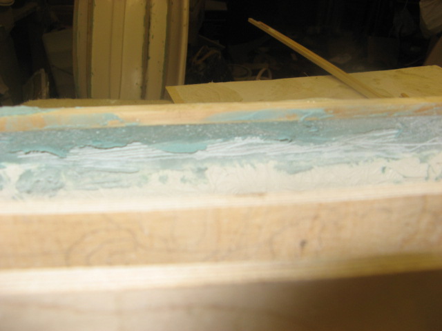  . |
|
  | |
Guest
Guest
 |  Subject: Re: A lifeboat build blog...........How a kit is made! Subject: Re: A lifeboat build blog...........How a kit is made!  Mon Jan 16, 2012 9:33 am Mon Jan 16, 2012 9:33 am | |
| There is now an amount of work and decision making before the sub deck and then the main decks are put on to the boats. When I originally designed the Anne Letitia Russell kit 18 years ago I made the well decks under the cabins to be removeable with the cabin tops, for access to the motors, batteries and rc gear. As the model was only 41 inches long space was a little restricted, but with these 3 at 46" and 51" long, space is a little better.It also, in this arrangement gave rise to the fact that in rough weather it would be susceptable to water getting into the hull as there were no combings around the aft end of the cabin. Not ideal but at the time, that was the only solution I could come up with...years and time gained experience now say differently. As such I decided to make the well decks as a pemanent fixed fitting, but possible with a removable floor to get to anything I needed, and as such measured from the plans the size, shape of the sides and constructed from 3mm ply, including a removable deck of 1.8mm ply backed up to keep the floor straight and flat, with the 3mm piece removed from the centre of the original deck. I also decided to make the back panel of the rear well deck on all 3 models removeable to access the servo and rudder arm for maintainance. This, once fitted would give access to parts of the hull. However once fitted in place to see, ( at th4 moment on the Mary Stanford only which is the biggest of the trio ) I begin to wonder whether the access in those positions is really needed and whether I should just stick with fixed decks with no noles in them. It would make the model far more water tight for heavy weather sailing should one want to. As you can see from the side views of the well decks they are angled to slide into the framework giving the floor the line of the sheer of the boat, particularly at the bow end of the boat. The frame work in the boat is now set rock solid and as needed, sections of frames have been cut out to facilitate the insertion of the well decks, before the support sub frame is glued in, which in certain places overlaps the well decks. What do you lot think? This set of photos shows the process of cutting through the floor of the well deck ( it was an after thought I had once I'd glued the well deck together).  the cut out from the well deck has been mounted onto a false floor of 1.8mm ply. 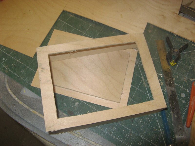 this picture shows the shape of the forward well deck so that the floor of the deck follows the shear line of the boat. 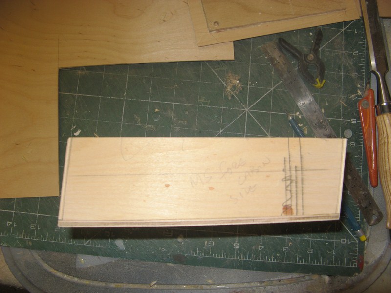 the following photos show the fore well deck in position and also fitted.note that sections of frame work have been cut out to take the assembly. All the parts are transfered to draughting paper for screen printing before gluing together.  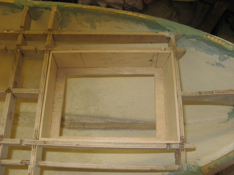  and the last set of are of the aft well deck.....note the access panel in the rear wall of the well deck for the rudder servo. 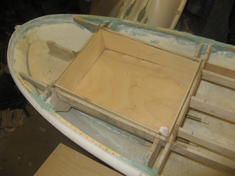  Side view of the rear well deck. 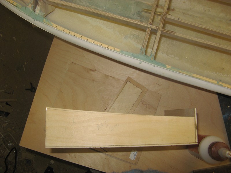 and finally an overall view of both well decks fitted. the long section in front of the rear well deck will be also access to the internals as this is covered by the engine casing.  . |
|
  | |
Footski
Master


Posts : 548
Join date : 2011-06-11
Age : 66
Location : Malaga, Spain
 |  Subject: Re: A lifeboat build blog...........How a kit is made! Subject: Re: A lifeboat build blog...........How a kit is made!  Mon Jan 16, 2012 1:12 pm Mon Jan 16, 2012 1:12 pm | |
| What do us lot think?
Well I reckon we might just be very impressed. Your well decks are a great idea and with the false floors will allow future 'messing about' with the internals.... | |
|
  | |
phil winks
Master


Posts : 583
Join date : 2011-06-12
Age : 68
Location : Taunton
 |  Subject: Re: A lifeboat build blog...........How a kit is made! Subject: Re: A lifeboat build blog...........How a kit is made!  Mon Jan 16, 2012 7:50 pm Mon Jan 16, 2012 7:50 pm | |
| I'm a little confused are the bottoms of the well decks removable or not I may be being a little thick here but humour me lol | |
|
  | |
Guest
Guest
 |  Subject: Re: A lifeboat build blog...........How a kit is made! Subject: Re: A lifeboat build blog...........How a kit is made!  Mon Jan 16, 2012 8:30 pm Mon Jan 16, 2012 8:30 pm | |
| At the moment they are phil, but I am at a quandry until I get the sub decks on each boat as to whether i have enough access to the hull without them being removeable or not..that is the question at the moment.
If there is enough room without removeable well decks then I'll adjust the drawings and instructions to suit....but it is a pondering at the mo.but thought it would be better to make them so at the moment rather than havwe to hack them all about later once fixed. |
|
  | |
Guest
Guest
 |  Subject: Re: A lifeboat build blog...........How a kit is made! Subject: Re: A lifeboat build blog...........How a kit is made!  Mon Jan 16, 2012 8:56 pm Mon Jan 16, 2012 8:56 pm | |
| I have been working on the two Watson's today. Both have a different set up and both needed careful planning and thinking about...like a grown up wooden jigsaw in 3D. The H F Bailey was very similar to that set up of the Mary Stanford and all that was needed was to take measurements of the two diferent cockpit well decks and to make sure that they fit where they should, and with a little trimming and cutting of the frames, they settled in to position neatly, ready for gluing in place shortly. The process will be written down step by step so that all aspects are covered for the builder, with help of diagrammes and photos. below is the H F Bailey complete with well decks ( again the floors have been left as removeable at the moment, but this might change once put together with decks fitted. I need the removeable deck on the rear cockpit on H F Bailey more than any other boat, because of the position of the rudder stock and where the servo will need to go to operate it.   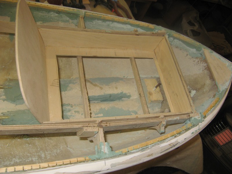  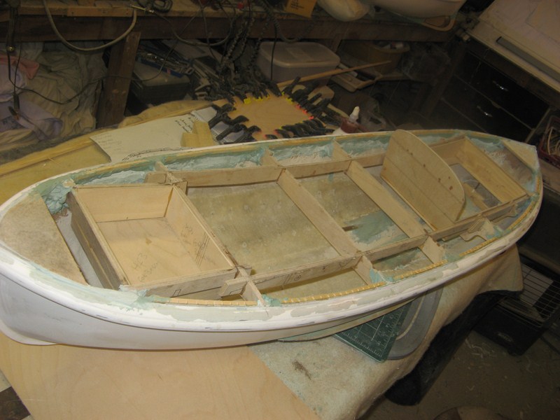 . |
|
  | |
Guest
Guest
 |  Subject: Re: A lifeboat build blog...........How a kit is made! Subject: Re: A lifeboat build blog...........How a kit is made!  Tue Jan 17, 2012 11:01 am Tue Jan 17, 2012 11:01 am | |
| The well decks on the Field Marshal and Mrs Smuts however were a little more tricky and needed a little thought. As on the H F Bailey, there is a bulkhead that has to fit into the cabin top without gaps, but this time is on the forward cabin, and patterns made of card were cut for it, gently slicing bits off the card to fit in the marked position once the cabin was on the deck......but this has to mate up with the well deck, and this is in a position where no supportive cross beams are available ( unlike the frames of the HF Baley and the Mary Stanford. So new "hangers" for want of a better word had to be devised and cut from 6mm ply, to both support the well deck ( as it isn't wide enough to fix and glue to the longitudinal beams) and were "in limbo" so to speak. Also the deck cross beam in picture 2 marked "G" had to be removed in the central section to accomodate the well deck. "Hangers" were measured,drawn and made and finally fixed to the position needed to support the forward well deck so that it's aft wall mated up with the forward bulkhead of the engine casing and the engine control bulkhead is in the correct position for the cabin. The cabin , as near as lines will show is almost the same as the aft cabin of the Ann Letitia Russell moulding and so this, in a chopped down form at the aft end of the cabin is to be used and mated up with the aft cabin. However both will be removeable seperately, giving reasonably good access into the hull. The pictures show a representative of the pieces cut ready to glue together to make one of the well decks on the F.M and Mrs S, and also show the aft well deck which is a similar build to any of the other cockpits that I have made for the other two boats. 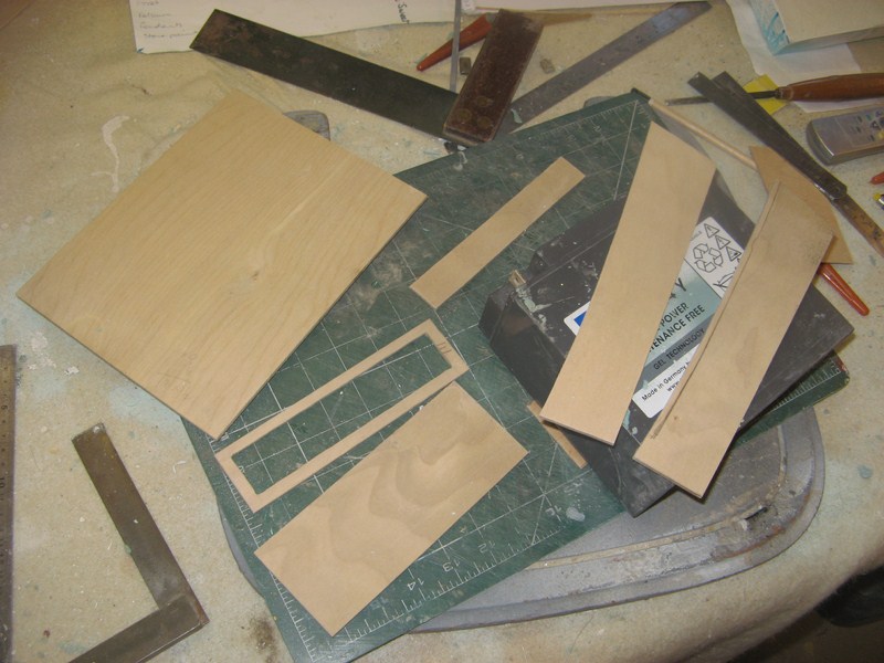  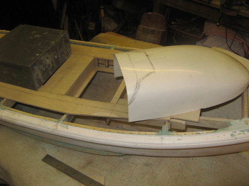  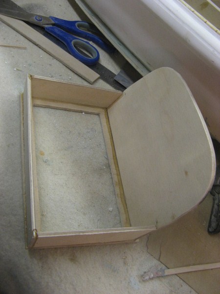 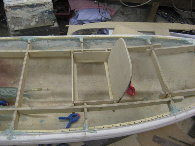    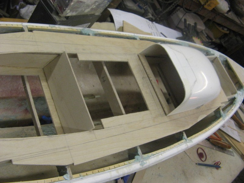 . |
|
  | |
Guest
Guest
 |  Subject: Re: A lifeboat build blog...........How a kit is made! Subject: Re: A lifeboat build blog...........How a kit is made!  Wed Jan 18, 2012 6:43 pm Wed Jan 18, 2012 6:43 pm | |
| I have found since fitting the servos on to the two Watson class boats that removeable floors in the rear well decks will be needed, but might have to be re designed before the drawings go off for printing, because of fittings both on the side walls of the cockpits and/or on the decks themselves, but this can be reworked once the well decks have been fitted. However, the access to the servos is reasonable, and as servos are pretty reliable, it is envisaged that access won't be needed too often. However the servo on the Barnett clas boat is well tucked away under a deck and as such a holder for the servo that is removeable is needed, and so, after trial and error and redesign a couple of times, I came up with a little holder that can be removed from the rear under deck space of the boat if need be. first few photos show the positioning of the Watson servos and the last few show the servo and holder for the Barnett, which will be covered all but for the working head by decks. 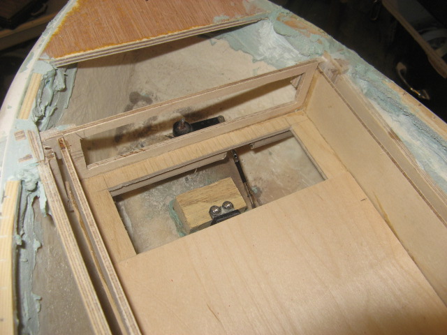    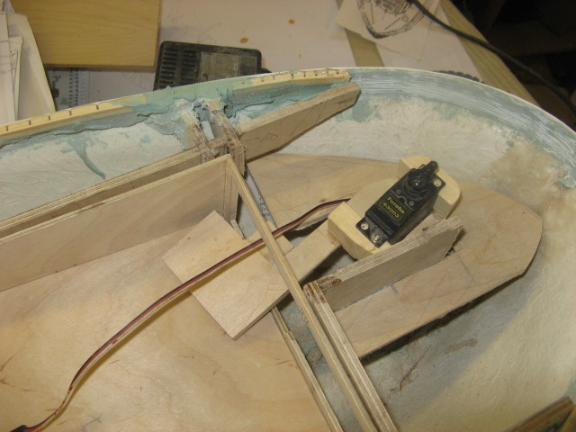  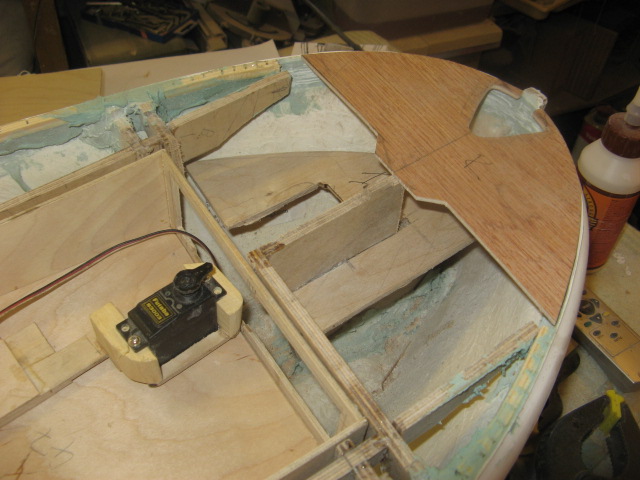  . |
|
  | |
Guest
Guest
 |  Subject: Re: A lifeboat build blog...........How a kit is made! Subject: Re: A lifeboat build blog...........How a kit is made!  Wed Jan 18, 2012 6:47 pm Wed Jan 18, 2012 6:47 pm | |
| |
|
  | |
phil winks
Master


Posts : 583
Join date : 2011-06-12
Age : 68
Location : Taunton
 |  Subject: Re: A lifeboat build blog...........How a kit is made! Subject: Re: A lifeboat build blog...........How a kit is made!  Wed Jan 18, 2012 9:05 pm Wed Jan 18, 2012 9:05 pm | |
| love the ingenious servo mount there Neil | |
|
  | |
Guest
Guest
 |  Subject: Re: A lifeboat build blog...........How a kit is made! Subject: Re: A lifeboat build blog...........How a kit is made!  Wed Jan 18, 2012 9:11 pm Wed Jan 18, 2012 9:11 pm | |
| the servo head actually steers the boat through a slide linkeage, and that is the only way that it can be seated as far to the rear of the boat as can be.
It will be set solid by two little nuts and bolts, nearer to the rear wall of the well deck which will be accesible with a struggle, but I don't envisage a problem with the servo...........just a failsafe if I ever did.
neil. |
|
  | |
Guest
Guest
 |  Subject: Re: A lifeboat build blog...........How a kit is made! Subject: Re: A lifeboat build blog...........How a kit is made!  Sun Jan 22, 2012 9:01 pm Sun Jan 22, 2012 9:01 pm | |
| |
|
  | |
Guest
Guest
 |  Subject: Re: A lifeboat build blog...........How a kit is made! Subject: Re: A lifeboat build blog...........How a kit is made!  Mon Jan 23, 2012 9:58 pm Mon Jan 23, 2012 9:58 pm | |
| Today was spent firstly sanding down the tops of the framework, sub decks and the bulwark edges and support beading all level with the subdecks and once that laborious job was made easy with my new toy, my sonic sander ( just unbelievable bit of kit) I set out making and cutting out card templates for the main decks of all three lifeboats, and then transfering those to 1.8mm birch faced ply, and cutting out. these templates take into account the access to the well decks, and when finally glued onto the sub deck and the beading around the edge of the hull will make a totally waterproof and very strong structure for the printed planked overlays to be added to give the boats that planked deck effect. before gluing the decks onto the boat they will be used to trace around for the screen prints and also for the shapes for the printed planked decks.a job for another day. the photos show in order, the marking out of the bow, and then stern patterns of the Mary Stanford, the patterns cut and waiting, the ply decks that have been cut from the card patterns ( H F Bailey) and the ply deck pieces in place and ready for gluing to the sub deck of the Mary Stanford. 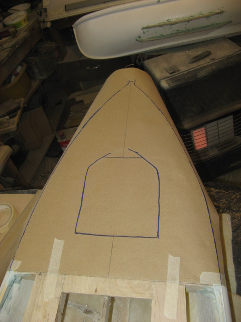     . |
|
  | |
scalloway41
Able Seaman


Posts : 36
Join date : 2011-06-11
Age : 59
Location : coventry
 |  Subject: Re: A lifeboat build blog...........How a kit is made! Subject: Re: A lifeboat build blog...........How a kit is made!  Mon Jan 23, 2012 10:11 pm Mon Jan 23, 2012 10:11 pm | |
| Stunning stuff following this with great interest. Look forward to each installments. Wish I had half your skills. Keep up the great work
| |
|
  | |
Guest
Guest
 |  Subject: Re: A lifeboat build blog...........How a kit is made! Subject: Re: A lifeboat build blog...........How a kit is made!  Mon Jan 23, 2012 11:09 pm Mon Jan 23, 2012 11:09 pm | |
| thanks mate.really appreciate the comments.
neil. |
|
  | |
Guest
Guest
 |  Subject: Re: A lifeboat build blog...........How a kit is made! Subject: Re: A lifeboat build blog...........How a kit is made!  Tue Jan 24, 2012 10:04 pm Tue Jan 24, 2012 10:04 pm | |
| Ohhh, for the power of batteries.....even dud ones. the main deck on the Mary Stanford was glued to the sub deck and bulwarks today using Gorilla glue......not only will it stick like the preverbial, but as it foams up it will adhere to any uneven surface underneath the main deck....kill two birds with one stone,so to speak.  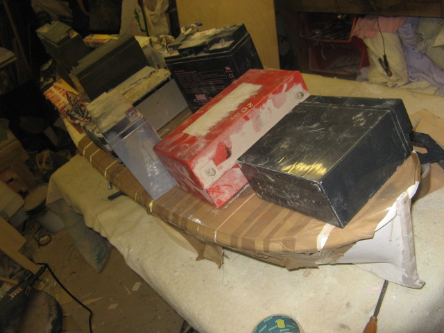 these two shots are of the second boat I glued up this afternoon...I sort of ran out o' batteries half way through and had to use more tape and 13mm picture frame pins to glue the rest of the deck down......hopefully by tomorrow afternoon will be able to start cleaning it all up, including the skegss and bilge keels etc.  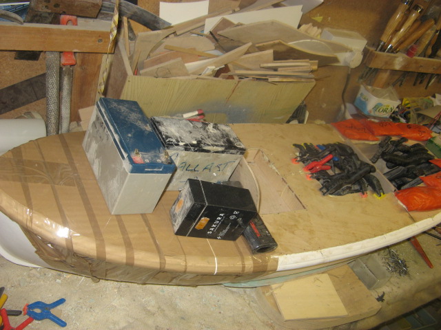 . |
|
  | |
phil winks
Master


Posts : 583
Join date : 2011-06-12
Age : 68
Location : Taunton
 |  Subject: Re: A lifeboat build blog...........How a kit is made! Subject: Re: A lifeboat build blog...........How a kit is made!  Wed Jan 25, 2012 8:02 pm Wed Jan 25, 2012 8:02 pm | |
| loving the detail here Neil.
Just one small money saving tip here for lovers of "Gorilla" Glue. if you pay a visit to the likes of jewsons or your local builders merchant and ask for a tube of polyurethane wood glue what you will get for approx £5 or £6 is a tube much like a silicone sealant tube but with a re-sealable cap about 5 times the size of the larger pots of gorilla glue for about 10% more money, it foams exactly the same and has the same waterproof and bond strength properties and to ease application on small joints I use a small ish syringe and decant from the larger tube this way if I forget to cap it after use I've only wasted a small amount and have really good control when applying to small joints. The brand I tend to use is everbuild. | |
|
  | |
Guest
Guest
 |  Subject: Re: A lifeboat build blog...........How a kit is made! Subject: Re: A lifeboat build blog...........How a kit is made!  Wed Jan 25, 2012 8:49 pm Wed Jan 25, 2012 8:49 pm | |
| thanks for that Phil.......it's the first time I've really used this type of glue....it is in fact a bottle that Steve tranter gave me ( and not gorilla glue.but exactly the same stuff) but god it sticks....even stuck my fingers to the silicon gloves I was wearing yesterday, lol |
|
  | |
Guest
Guest
 |  Subject: Re: A lifeboat build blog...........How a kit is made! Subject: Re: A lifeboat build blog...........How a kit is made!  Wed Jan 25, 2012 9:01 pm Wed Jan 25, 2012 9:01 pm | |
| the decks have now all been fitted, and I'm just waiting for the deck on the HF Bailey to cure before taking the tapes and weights off before trimming up. the edges of the deck to bulwarks have been trimmed with a nice sharp bevelled edge chisel and then filled with polyester filler. the start has been made to trim around the cockpit accesses and one one of the shots can be seen a scrap piece of 1.8mm ply that acts as a support for the two pieces of the deck ( port and starboard pieces) to mate up to each other without any sagging of either side. But the thing that always every time gets to me about a classic lifeboat is the beautiful sheerline of the bulwarks top from bow to stern.....such a gracefull and yet business like and powerfull shape to them..and these three are no exception. To me they are far more graceful than the modern fast afloat boats, and although not as powerful, fast or safe to be in..they still went out in the same dreadfully awful and pitiless seas that the modern boats with all their protection can muster, to do one thing...and that was to put their own lives on a knife edge to save others.........and it gives me unbelievable pride to be able to re create models of these boats for pleasure. The whole of each boat will now be sanded and got ready for a few coats of paint. neil. 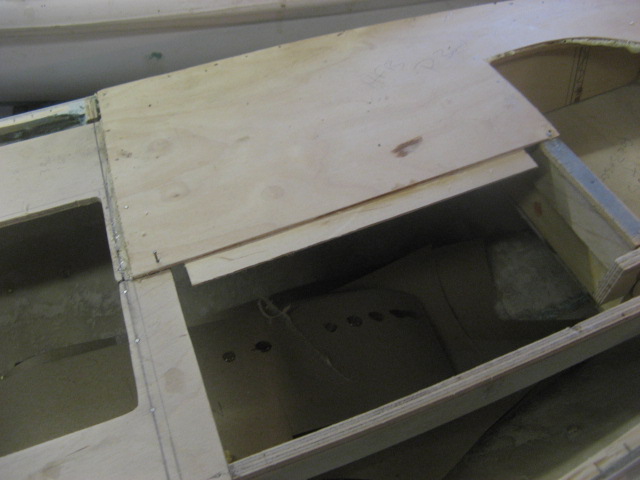 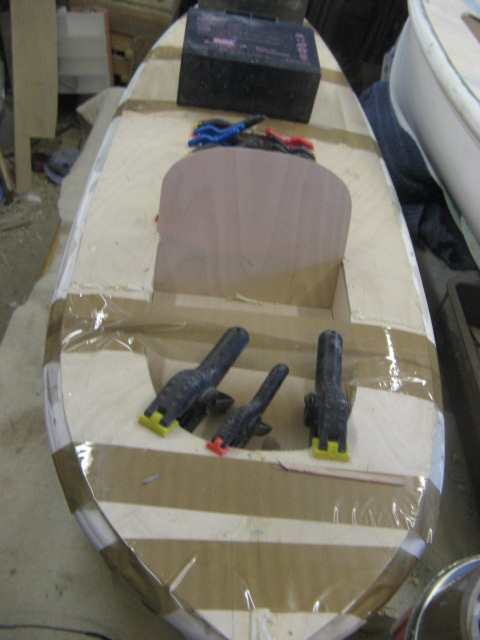 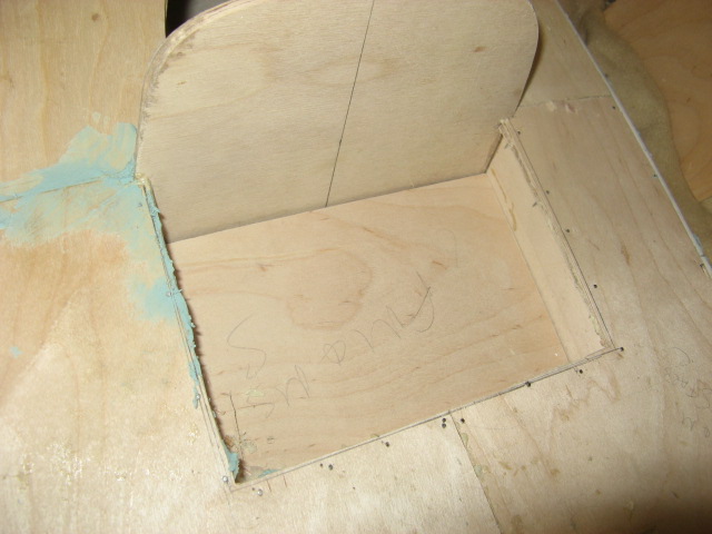 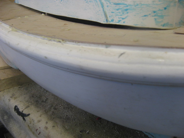 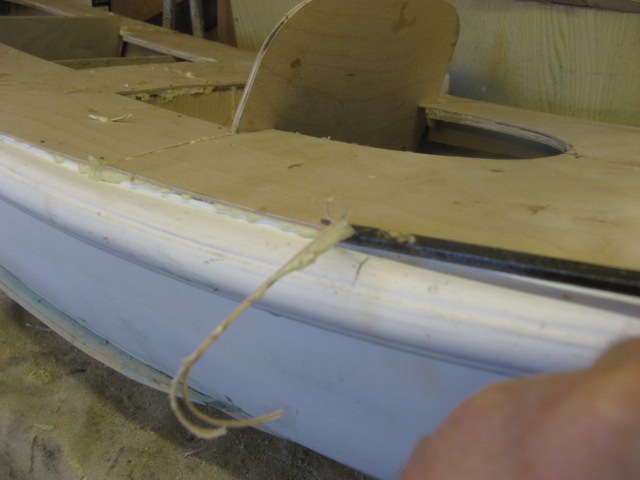 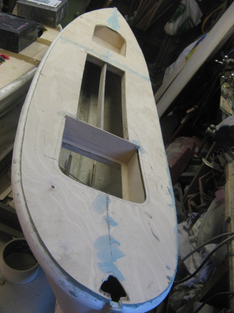 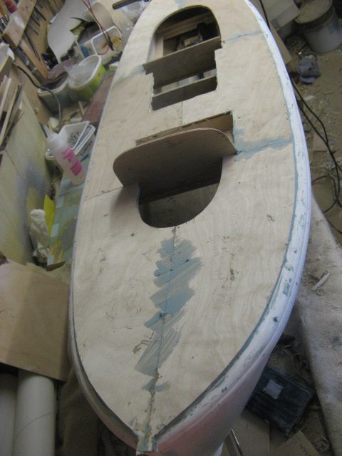 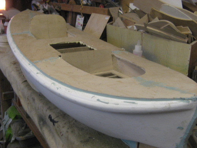 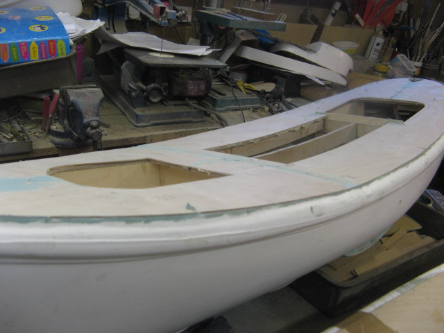 . |
|
  | |
Footski
Master


Posts : 548
Join date : 2011-06-11
Age : 66
Location : Malaga, Spain
 |  Subject: Re: A lifeboat build blog...........How a kit is made! Subject: Re: A lifeboat build blog...........How a kit is made!  Wed Jan 25, 2012 9:15 pm Wed Jan 25, 2012 9:15 pm | |
| Wonderful as usual Neil.. | |
|
  | |
phil winks
Master


Posts : 583
Join date : 2011-06-12
Age : 68
Location : Taunton
 |  Subject: Re: A lifeboat build blog...........How a kit is made! Subject: Re: A lifeboat build blog...........How a kit is made!  Wed Jan 25, 2012 9:20 pm Wed Jan 25, 2012 9:20 pm | |
| That glue from Steve tranter is exactly what I'm talking about neil and from his web site looks like it comes in the same silcone type tubes too | |
|
  | |
Guest
Guest
 |  Subject: Re: A lifeboat build blog...........How a kit is made! Subject: Re: A lifeboat build blog...........How a kit is made!  Wed Jan 25, 2012 9:33 pm Wed Jan 25, 2012 9:33 pm | |
| It's good stuff too, Phil..can recommend it, but as it does expand, it certainly needs clamping and weighing down. |
|
  | |
phil winks
Master


Posts : 583
Join date : 2011-06-12
Age : 68
Location : Taunton
 |  Subject: Re: A lifeboat build blog...........How a kit is made! Subject: Re: A lifeboat build blog...........How a kit is made!  Thu Jan 26, 2012 8:56 pm Thu Jan 26, 2012 8:56 pm | |
| Yep the firmer the clamping the stronger the joint and as for waterproof qualities it is licensed for use on marine vessels so salt water resistant as well as fresh | |
|
  | |
Guest
Guest
 |  Subject: Re: A lifeboat build blog...........How a kit is made! Subject: Re: A lifeboat build blog...........How a kit is made!  Thu Jan 26, 2012 9:18 pm Thu Jan 26, 2012 9:18 pm | |
| |
|
  | |
Guest
Guest
 |  Subject: Re: A lifeboat build blog...........How a kit is made! Subject: Re: A lifeboat build blog...........How a kit is made!  Fri Jan 27, 2012 1:02 pm Fri Jan 27, 2012 1:02 pm | |
| |
|
  | |
Guest
Guest
 | |
  | |
Guest
Guest
 |  Subject: Re: A lifeboat build blog...........How a kit is made! Subject: Re: A lifeboat build blog...........How a kit is made!  Fri Jan 27, 2012 10:13 pm Fri Jan 27, 2012 10:13 pm | |
| the second lifeboat, the H F Bailey was again, not following the rules of fair play. the aft cockpit behind the engine room bulkhead was reasonably straight forward with just the bending of the ply onto the rear wall, which was again facilitated easily by using a cut of the 1.8mm ply across the grain of the sheet . However the foreward part of the rear cabin assembly was not as easy. because of the slope of the forward engine casing sides, verticla combings would not be an option. So I used two lengths of Obeche timber and sloped a section of this timber to the slope of the engine casing side, leaving a flat flange to but upto the side where the combing wuld normally glue to. I then cut and shaped a piece, labelling it and put it in the box of "odd bits" that will be eventually machined as pieces to put in the kit, and therefore as a pattern for the pieces used, can be copied and manufactured, for ease for the builder. The front face of this combing could then be made as a normal virtical piece from 3mm ply. Finally the two curved pieces of 1.8mm ply just forward of the engine room bulkhead were, again made from 1.8mm ply and glued and pinned to the wall of the access hole. Luckuly, the forward cabin on each of the two boats H F Bailey and Mary Stanford are fixed and therefore don't need combings fitted. 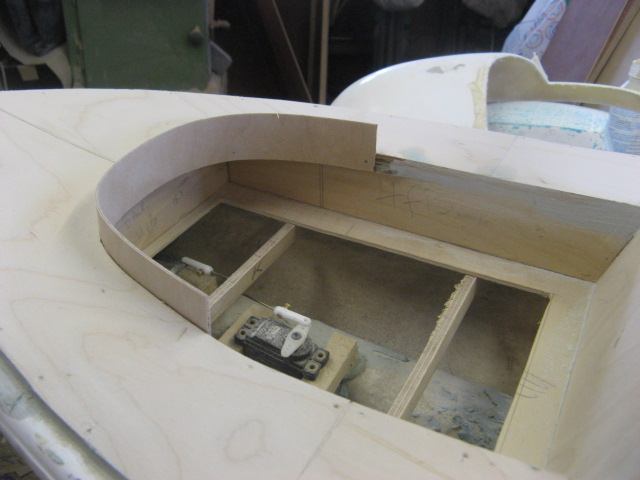  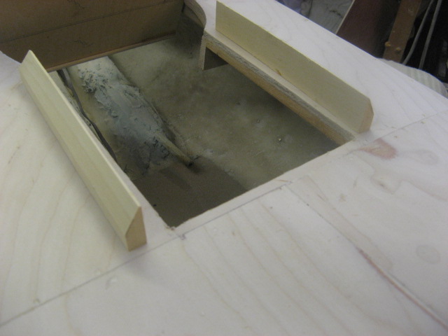     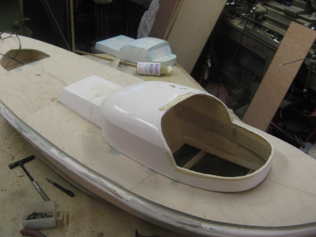 . |
|
  | |
Guest
Guest
 |  Subject: Re: A lifeboat build blog...........How a kit is made! Subject: Re: A lifeboat build blog...........How a kit is made!  Sat Jan 28, 2012 10:16 pm Sat Jan 28, 2012 10:16 pm | |
| |
|
  | |
Footski
Master


Posts : 548
Join date : 2011-06-11
Age : 66
Location : Malaga, Spain
 |  Subject: Re: A lifeboat build blog...........How a kit is made! Subject: Re: A lifeboat build blog...........How a kit is made!  Sun Jan 29, 2012 7:56 am Sun Jan 29, 2012 7:56 am | |
| I just love this thread...  | |
|
  | |
Guest
Guest
 |  Subject: Re: A lifeboat build blog...........How a kit is made! Subject: Re: A lifeboat build blog...........How a kit is made!  Mon Jan 30, 2012 1:27 pm Mon Jan 30, 2012 1:27 pm | |
| cheers Barry. The cabins for the two Watsons were also fitted this morning, using the same pencil guage to get the cabin bases fitting exactly to the sheer line of the deck. The engine casing of the HF Bailey and the Field Marshal and Mrs Smuts caused a little problem, as (when I moulded it some years ago, rather heavily I must add) the inside corners of the engine casing were rather "rounded" with a goodly use of resin and mat and so the combings on the deck had to be rounded to accomodate this minor hickup........but hey!?.............that's modelling, and little faults and tribulations with hand made kits will always occur, and certainly doesn't hopefully detract from the overall kit. Also the engine room bulkhead on both the two watsons had to be sanded down on the top and side edges as the cockpit bases lost a little from the bottom line of grp. This compensated that loss and allowed the cockpit to sit nicely onto the deck. Perhaps if it does, those modellers should stick to Airfix/Revelle plastic models! Once fitted it was time to cut out the openings into the cockpits. To do this, the rims of the cockpit openings were first marked with a pencil line 4mm from the outside edge and then masked off with masking tape to stop the drill bit from straying and sliding across the grp. The forward cabin of the Field Marshall and Mrs Smuts is in fact using (as it is almost exactly the same shape as the rear cockpit on the Anne Letitia Russell......another kit in the range from metcalf Mouldings) a cockpit from the aforementioned kit, but needs to be cut and modified, which was done this morning. Not one for using a saw on grp, I drilled the perimeter of the opening on the inside of the line, and then using the side of the drill bit............the flukes, I reamed out the waste grp to form the opening. This then revealed the cockpit edge as a jagged strip, which will be filed to the masked line for a smooth edge.    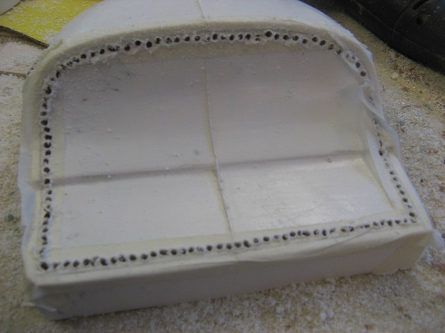 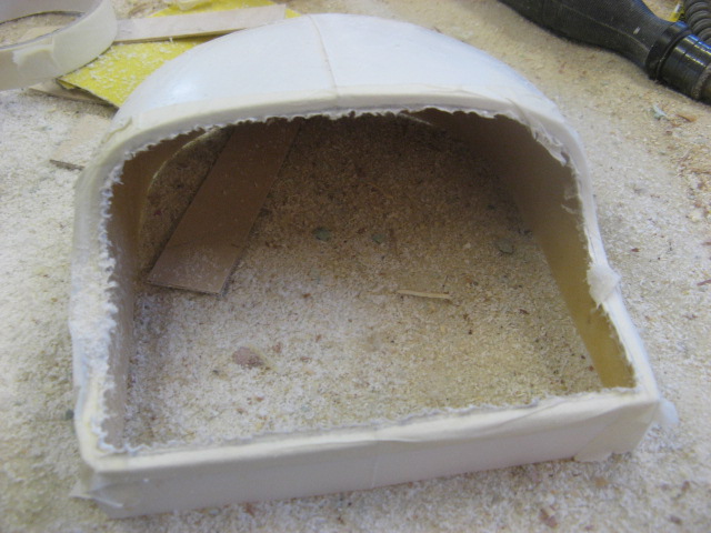 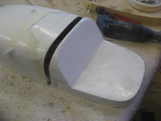   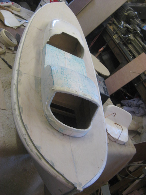   . |
|
  | |
Guest
Guest
 |  Subject: Re: A lifeboat build blog...........How a kit is made! Subject: Re: A lifeboat build blog...........How a kit is made!  Mon Jan 30, 2012 9:02 pm Mon Jan 30, 2012 9:02 pm | |
| And now, just as a little side line, after working on three hulls/cabins altogether, which can get monotonous at times I decided to get on with a little job that I'd been putting off for a while...not because I didn't want to do it......I enjoy laithe work, but just because it was probably the last fitting that I needed to make, one that I had forgotten I needed, and one which needs moulding in rubber ( a sometimes messy job) and then casting in resin.....and this is the bummer...........I've run out of polyrethane resin and would have to order some, forr a little job, knowing that I probably won't need to use it any more than once, and once open it has a lousy shelf life.....oh well...........just bite the bullet and order a teeny amount. So what is the fitting ...............it's a pillar and base to hold the forward/reverse wheel for the Field marshall and Mrs Smuts....the other two boats, and the Anne Letitia Russel and the liverpool class lifeboat all have them mounted on the engine room bulkhead on a consol....the FM has them on pillars in the open forward cockpit. The wheel atop the pillar is generic with the other boats, so I just needed to turn the pillar and the collar base from brass on my trusty ML7. Then I mounted them in plastecine in a lego box and poured the first half the mould with RTV30 rubber.......I'll pour the other half tomorrow.............but get this folks. When you put the second layer of rubber onto the first, you first normally spray the hardened rubber with a release agent wax...........I ran out a couple of months ago, so rang Tiranti's of Reading where I normally get my supplies of rubber and asked for them to send me a new can of spray release agent................"sorry we can't" said Tiranti's......" because of the new laws on conveying spray cans, we can't send the cans any more".........is this HSE gone mad or what??? 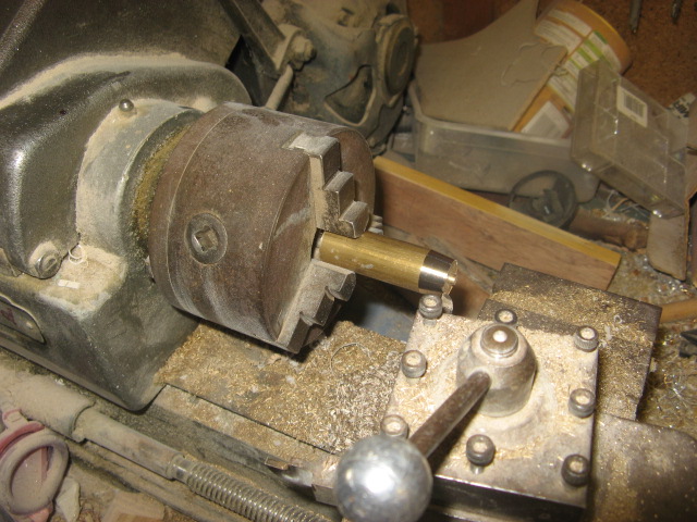 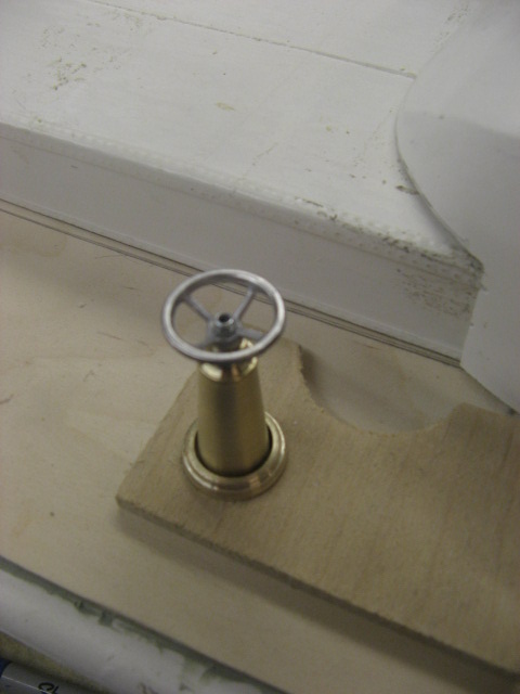 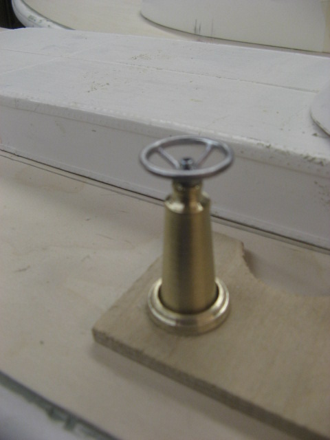 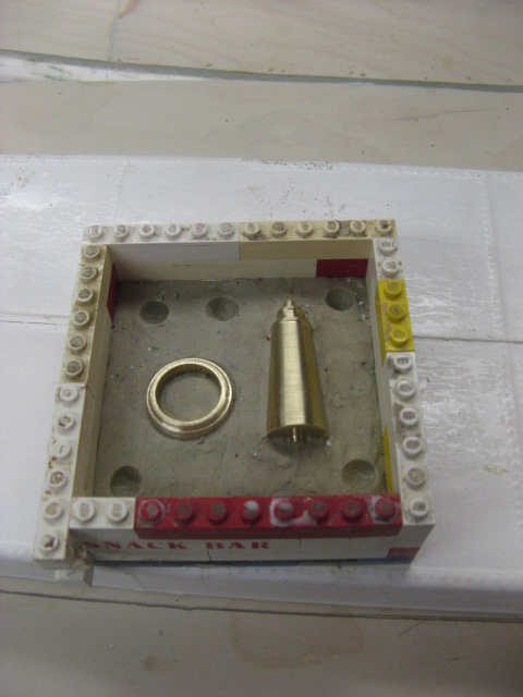 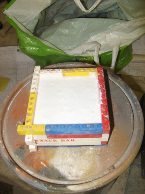 . |
|
  | |
Guest
Guest
 | |
  | |
Guest
Guest
 |  Subject: Re: A lifeboat build blog...........How a kit is made! Subject: Re: A lifeboat build blog...........How a kit is made!  Sat Feb 04, 2012 10:30 pm Sat Feb 04, 2012 10:30 pm | |
| Now that all the cabins fit onto their combings and the decks reasonably well, it's time to fit the "king plank"....the centre plank on the deck running from stern to bow. It is interupted by the cabind but it is a centre point to which the deck planks are laid. However on these boat models the kit will be supplied with a printed deck overlay and they will but up to that King plank. This was made from a strip of 1.8mm ply 10mm wide, just wider than the printed ply planks on the overlays, and was glued down with aliphatic resin glue. As I had made the original main decks from templates that I had drawn and cut from card, I used these again to make the templates for the overlay decks. They had to be marked and cut down as they have a gap around the combings for the cabins to sit between and also a small space between the edge of the bulwarks and the deck, and so all templates had again to be marked , cut to size and then drawn on to 1.8mm ply before the ply was cut out and finally offered up to the boat for final tweaking. The will then be marked as per plan in pencil, lightly with all planking and hatch markings, before being given two or three coats of cellulose sanding sealer to seal the markings in. Once rubbed down with wyre wool the markings will be drawn over with black draughting pen and ink as would the planks look after being caulked. Finally each piece will be photocopied at my friendly print shop, and it will be the photocopies of the deck overlays which will be traced onto draughting paper for making the screen prints for the production deck overlays.........a bit of a long drawn out( excuse the pun) process but aty least I'll know that the overlays will fit to the decks the way they should, if the model is built the way it should be. The photos shown below in order show the king planks being laid where the deck and cabins allow, the templates for the overlays,the overlays on the FM & Mrs S, and then the overlays of Mary Stanford, Field marshall and Mrs Smuts and H F Bailey, in that order. 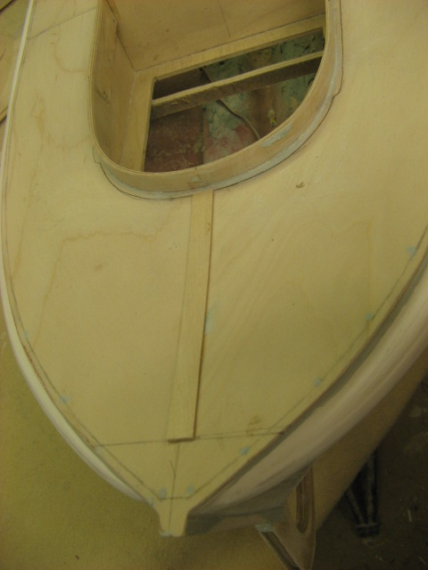 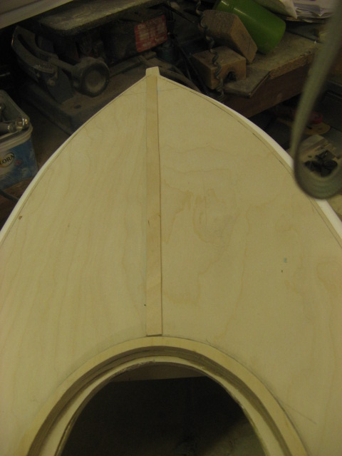 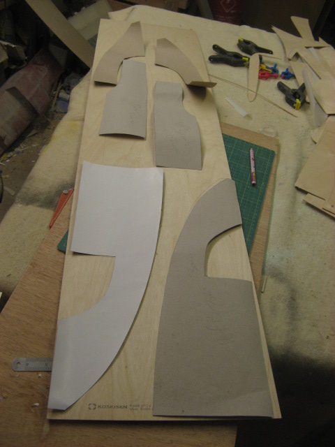 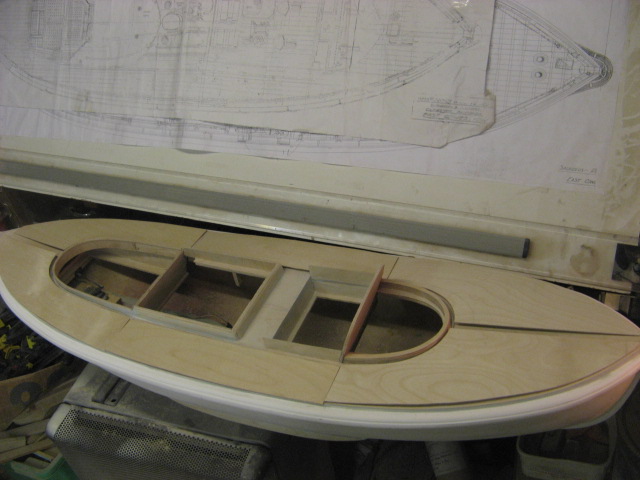  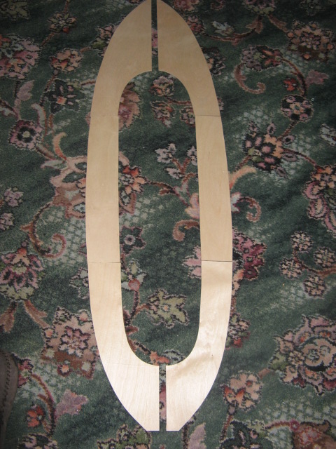 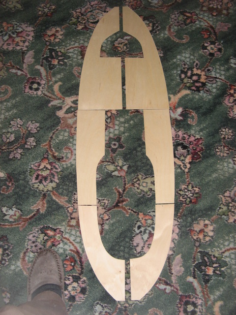 |
|
  | |
Footski
Master


Posts : 548
Join date : 2011-06-11
Age : 66
Location : Malaga, Spain
 |  Subject: Re: A lifeboat build blog...........How a kit is made! Subject: Re: A lifeboat build blog...........How a kit is made!  Sun Feb 05, 2012 7:30 am Sun Feb 05, 2012 7:30 am | |
| They really are coming along a treat Neil..  | |
|
  | |
Guest
Guest
 |  Subject: Re: A lifeboat build blog...........How a kit is made! Subject: Re: A lifeboat build blog...........How a kit is made!  Sun Feb 05, 2012 8:25 am Sun Feb 05, 2012 8:25 am | |
| they'll look a whole world of diferenceonce I get those printed decks on.....looking forward to it. |
|
  | |
Guest
Guest
 |  Subject: Re: A lifeboat build blog...........How a kit is made! Subject: Re: A lifeboat build blog...........How a kit is made!  Mon Feb 06, 2012 8:40 am Mon Feb 06, 2012 8:40 am | |
| Today I've been marking out the planking, filler cap holes, deck lights, bollard bases and the access hatches on the deck overlays. To get the planks marked off in line running the full length of each boat, I marked the measurements for the planks on a scrap piece of ply, and then laid a 600mm steel rule on a building board. I could then tape down the piece of timber so that the edge making up to the king plank was fitted snugly to the steel rule( which took the place of the King plank.) then marking off the plans for measurement, all the small areas were first marked on, and finally the planks marked onto both the bow and stern pieces of overlay. Finally I inserted the centre section of each deck side, and ran the plank lines from these two pieces over the centre piece, thus getting the plank lines running through the whole deck in a good straight line. All 18 pieces of deck will now be taken off to the print shop tomorrow for photocopying, so that I can eventually trace them onto draughtingpaper for making screen prints for the kits. Quite a monumental task, and I finally put the last piece down at 23.45 hours......and I started the process at 14.00 hopurs yesterday afternoon, with a break of 30 minuted for my evening meal...................boy, did I sleep well last night!!     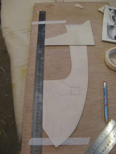 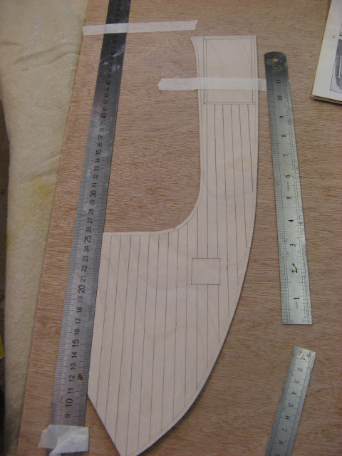  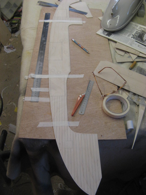 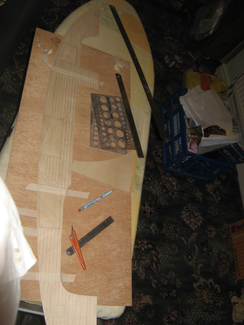 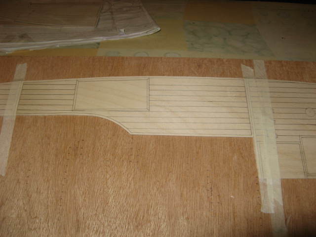 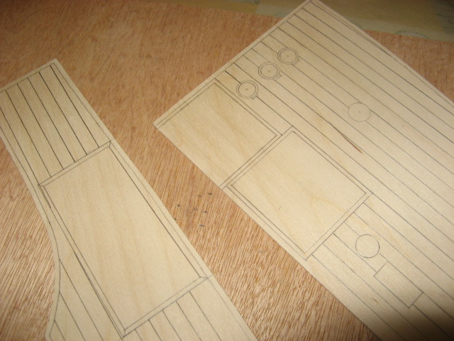 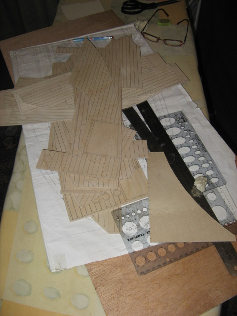 . |
|
  | |
Tug--Kenny
Lost But Never Forgotten R.I.P

Posts : 284
Join date : 2011-06-11
Age : 82
Location : Newport, South Wales,UK
 |  Subject: Re: A lifeboat build blog...........How a kit is made! Subject: Re: A lifeboat build blog...........How a kit is made!  Mon Feb 06, 2012 12:22 pm Mon Feb 06, 2012 12:22 pm | |
| Smashing Neil.  We never realised the work involved. Following with great interest. ken | |
|
  | |
Guest
Guest
 |  Subject: Re: A lifeboat build blog...........How a kit is made! Subject: Re: A lifeboat build blog...........How a kit is made!  Mon Feb 06, 2012 12:44 pm Mon Feb 06, 2012 12:44 pm | |
| cheers Ken. took the timber overlays to my mate's at the printers this morning. He photocopied them to A3 size paper, which will now be traced, giving the exact size of deck and planks, etc for screen printing. the timber overlays can now be glued to the main decks. 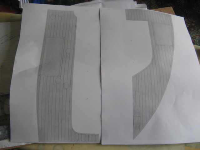 . |
|
  | |
tattooed
Able Seaman


Posts : 45
Join date : 2011-06-30
Age : 61
Location : Bristol
 |  Subject: Re: A lifeboat build blog...........How a kit is made! Subject: Re: A lifeboat build blog...........How a kit is made!  Mon Feb 06, 2012 3:07 pm Mon Feb 06, 2012 3:07 pm | |
| fantastic workmanship neil but then again wouldn't expect anything less from a master model builder like yourself , i'm watching these builds with great interest keep up the good work | |
|
  | |
Guest
Guest
 |  Subject: Re: A lifeboat build blog...........How a kit is made! Subject: Re: A lifeboat build blog...........How a kit is made!  Mon Feb 06, 2012 3:23 pm Mon Feb 06, 2012 3:23 pm | |
| Hi andy.
long time no hear..how are you.
neil/ |
|
  | |
tattooed
Able Seaman


Posts : 45
Join date : 2011-06-30
Age : 61
Location : Bristol
 |  Subject: Re: A lifeboat build blog...........How a kit is made! Subject: Re: A lifeboat build blog...........How a kit is made!  Mon Feb 06, 2012 4:33 pm Mon Feb 06, 2012 4:33 pm | |
| i'm very well thanks neil , i look into the forum every day to see what everyone is doing and to read up on your fantastic builds they really are a work of art and a true credit to you .
i'm going to ask you if it's possible to make the nose/rear cones for some torpedo's that are going on a sub that i'm just about to start i can either pay you for them or trade you for them ie stainless wire, sheets of nylon , have loads of the ikea blinds also that double sided tape you use we have rolls of that 1inch and 2 inch wide in 30mtr rolls just tell me which way you'd like to go mate .
did you manage to sell the ambulance boat in the end, i'm still trying to sell the beamer keep up the good work neil and most of all keep safe
Andy | |
|
  | |
Guest
Guest
 |  Subject: Re: A lifeboat build blog...........How a kit is made! Subject: Re: A lifeboat build blog...........How a kit is made!  Tue Feb 07, 2012 1:50 pm Tue Feb 07, 2012 1:50 pm | |
| hi, andy......just send me what you want doing.. or if you have one that i could put itnto a mould for you that'd be even easier.............shape, size .............what ever and I'll see if I can do it....don't want anything mate........
yes, with regards the Ambulance launch..........the directer who knew nothing about it all as he'd been away on business sorted it when he got back......"had a long talk" to the manager who had cocked it up....so alls well that ends well. |
|
  | |
Guest
Guest
 |  Subject: Re: A lifeboat build blog...........How a kit is made! Subject: Re: A lifeboat build blog...........How a kit is made!  Tue Feb 07, 2012 1:51 pm Tue Feb 07, 2012 1:51 pm | |
| this morning I have been preparing the printed deck overlays for gluing onto the main deck. This entailed sealing in the printwork of planks etc with cellulose sanding sealer. once dried and rubbed down, I drilled the holed in the due places marked for the petrol filling scuttles and bilge pump outlets which come as white metal fittings. Drilling undersize with a forstner bit in my pillar drill, ( so as not to chip the edges of the timber ) I then enlarged the holes with 120 grade grit paper, wound into a tube around a piece of dowel rod and sanded the holes to accept the fittings. Finally I cut the tags for the fittings with a craft knife. 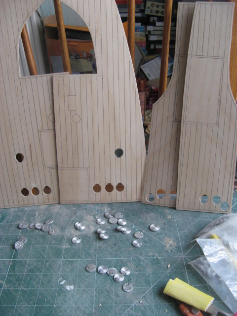 |
|
  | |
Sponsored content
 |  Subject: Re: A lifeboat build blog...........How a kit is made! Subject: Re: A lifeboat build blog...........How a kit is made!  | |
| |
|
  | |
| | A lifeboat build blog...........How a kit is made! |  |
|
